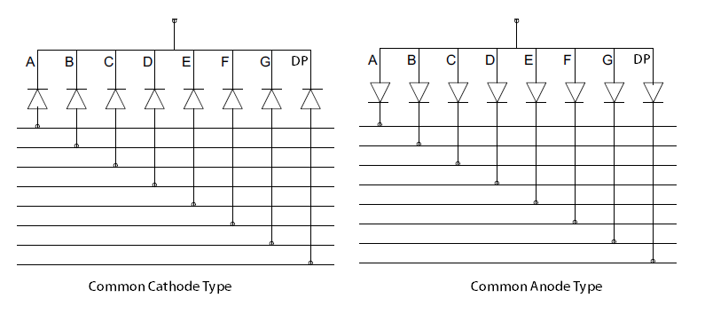

So the common pin can be simply connected to Arduino board Pin 9 & is made HIGH always. In this circuit, a common cathode type 7 Segment Display is used.

For instance, if you want to display numeral ‘1’ then both the segments like b & c need to be switched ON & the remaining segments will be switched off. If we disconnect the power, particularly for ‘g’ then it will display as ‘0’. Once the power of a 7-segment display is ON then an 8 number will be displayed. Based on the seven-segment type, the segment pins are applied with logic zero or high & in the same method to the common pins also.
#COMMON CATHODE 7 SEGMENT DISPLAY PIN DIAGRAM SERIES#
Once these pins are forward biased in a series then it will display the specific alphabet or numeral. The display can be controlled through freely left pins. The working of the 7-segment display can be done by glowing the necessary individual LEDs within the digit. When we want to turn on any particular segment then we need to apply logic zero on the corresponding cathode. To interface a common anode type to a microcontroller then the Cathodes of each segment are connected through appropriate port pins of the microcontroller. In order for a segment to light up, the corresponding cathode terminal will be grounded and the common anode terminal is provided with +5V source voltage. In this type, all LEDs share a common anode terminal while each cathode terminal is connected to a different segment. Please refer to this link for 7-segment Display MCQs 7 Segment Display Common Anode: There are two main types of 7-segment displays: The only difference is that they have 8 pins rather than 2 pins because each of the 7 LEDs has its own pin along with a common cathode or anode pin. in series with a current limiting resistor). 7-segment displays are connected to the microcontroller in the same way as LEDs (i.e. Pin10 (g): This pin is used to control the middle LED of the displayħ Segment Displays which have 7 LEDs are arranged in a way that can display numbers from 0-9.Pin9 (f): This pin controls the top left LED of the display.Pin8 (Com): This pin is connected to Vcc/GND based on display type.Pin7 (a): This pin is used to control the topmost LED of the display.Pin6 (b): This pin controls the top right LED of the display.Pin5 (DP): This pin controls the decimal point LED of the display.Pin4 (c): This pin controls the right bottom LED of the display.Pin3 (Com): This pin is used to connect to Vcc or Ground-based on display type.Pin2 (d): This pin is used to control the bottom-most LED of the display.Pin1 (e): This pin is used to control the left bottom LED of the display.


 0 kommentar(er)
